Friday 28 December 2012

The Festive Season

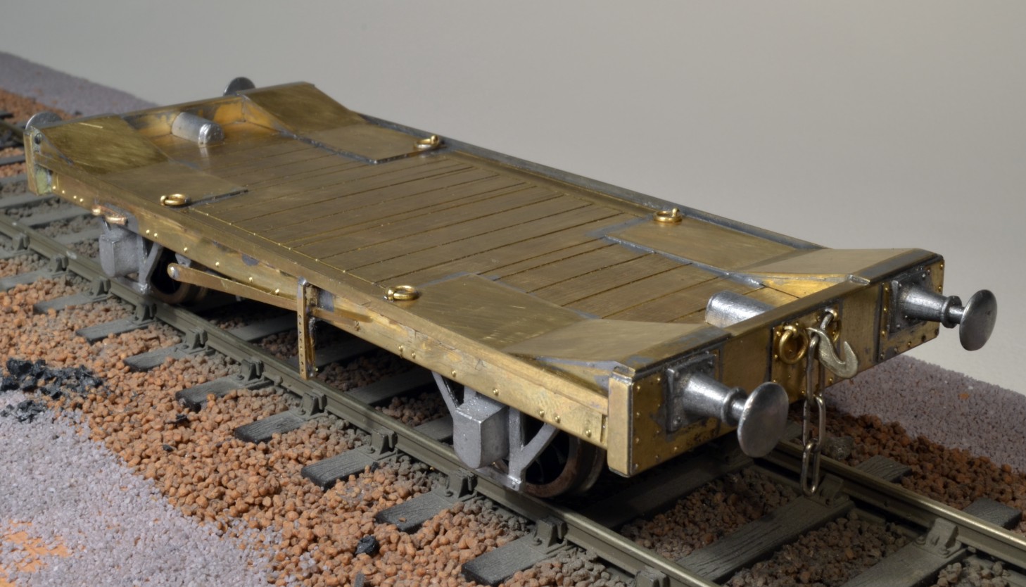
NBR / LNER Agricultural Implement wagon Dia 99

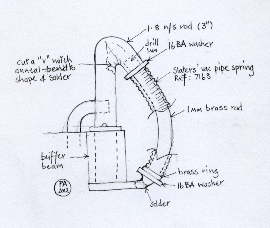
The Festive Season has not proved unduly distracting this year, I told the relations I was in Australia and spent the time saved in the studio building this NBR "Imp", with a minimum of modification, from a Celtic Connections kit. It runs well on a solid wheelbase. The buffers and draw hook are solid too, not sprung. I don't think its a problem to have a wagon with solid buffers in a train, though it might be a good idea to put it between two wagons with sprung buffers.


Fordson "F" awaiting tracks

Fordson "F" Trackpull Crawler


This is the load for the NBR "Imp"...a Fordson "F" crawler tractor built from a white metal and brass kit by "The Model Company" of NZ. I bought it from ABS models at a show last year. It's a well engineered product with plenty of fine detail, takes a bit of building though. You can build it with steel field wheels too, as I did myself some time ago; this alternative version can be seen in the "Wagons" section of the Blog.


Fordson "F" Crawler Tractor load on NBR "Imp".


The tractor is the 1926 version so I'll probably finish the wagon in LNER livery...the earlier NB livery includes a fearsome amount of script lettering along the solebar which I don't fancy confronting. I'll have to contrive some rope lashing and wooden blocks and wedges that I know the railway company would've used to steady the load when in transit.

As I mentioned in my previous Post... I bought Geoff Holt's book "Locomotive Modelling", wrapped it up and opened it Christmas Day. It was indeed a slim volume but it was a good buy, a great book if a trifle overpriced. I'll be ordering vol. 2 without a doubt...good one Geoff!

What else was lurking under the Christmas Tree?  Well, the only thing of modelling interest was a Meteor Models' 14 Ton Rail Tank kit which looks a decidedly interesting build. Oh... and I bought the wifey a Highland Railway timber wagon kit from Invertrain which I thought she'd enjoy seeing going round...I think I'll probably build it for her. 

Sunday 16 December 2012

A Slim Volume and a Running day at CD0GG.

On Friday a rather slim package dropped through my letter box, I knew it was Geoff Holt's new book on locomotive building...Volume 1. I'd only ordered it the day before at some considerable expense. This was good service on the part of the bookseller, however I was a little taken aback by the slimness of the envelope it came in, it seemed as if the contents were no thicker than a magazine. I viewed it with some trepidation and considered opening it but gave it to my wife to wrap for Christmas Day. I will give my reactions on opening the said packet in a later posting.

On Saturday I took my completed Coal Tank to the Members' Running Day at CD0GG at their premises in the basement of Carlisle Citadel Station.

LNWR Coal Tank at CD0GG

 The superbly modelled scenic section of the Carlisle group's generous layout makes a fine backdrop against which to photograph models.  The Coal Tank is running through the station with a short train comprised of my Highland Railway D9 composite coach and a well modelled Maryport & Carlisle Railway Horsebox belonging to one of the members. The engine ran very well and I was pleased with her performance. I've a backlog of models awaiting the paint shop here in my workshop so a painting session is my next priority. I've already stripped my HR D19 coach down ready to paint so I'll start with that and afterwards my long neglected "Wee Ben".


NW Coal Tank and HR composite coach glide smoothly through the station at CD0GG.

Coal Tank waits in the sidings at CD0GG
I modelled the fireman from photos of  typical Coal Tank crew, he doesn't have a uniform or railwayman's cap but wears an old flat cap and his "working clothes". The driver's out of sight on the left...both the crew members are now available in my "Heroes of the Footplate" range and will be added to the Website soon.   

Wednesday 5 December 2012

HR D9 Coach, More progress


HR D9 Chassis wheel-springs and hangers.
 
When assembling and mounting the springs and their hangers on the solebars the sequence of work is important. The spring-hangers and the leaf-springs, along with a length of rod on which four brass discs, a washer and a terminal nut are mounted are soldered together in the flat. Then the spring-hangers are bent to shape and soldered in place on the bottom of the solebar. The centre wheel-springs are different to the outer ones and are more of a fiddle to build, however the sequence of assembly remains the same.


Buffers, couplings and safety chains on the buffer beam
 The couplings are made from castings by CPL and work prototypically. The safety chains I made myself from 0.6 wire; the hanger is a short pattern brass hand rail knob with the sides of the head flattened with a file and the hole enlarged and countersunk.


HR D9 Third Class compartment.

HR Third Class compartments were designed to seat ten passengers, it looks like a tight squeeze. My passenger is from my Heroes of the Footplate range... SP2 Seated Gent 3rd Class passenger. I haven't made any First Class passengers yet though I intend to do so. The inner skin of the coach is in place and this forms a slot, between it and the outer skin, into which the glazing will slide. I'm waiting for some cast brass grab-handles from LGM but they'll not be available until after Christmas, so I can't solder the inner skin in place yet.


HR D9 Roof fittings.
When the oil lamp that lit each compartment was removed a bung was fitted in the hole to make it watertight, a lamp top and a bung are in place on the coach roof; these are castings from my own range of HR accessories which you can see at  http://www.borderminiatures.com/

Monday 19 November 2012

Highland Railway D9 Coach...progress


Lochgorm Kits' HR D9 Luggage Composite Coach

 The coach body is pinned down to a piece of MDF to keep it flat. I've added a complete floor to the coach as well as fitting the four partitions that will stabilise the structure. The ends are now double, forming a slot into which a tongue soldered to the roof will locate to keep it in place; none of the roof bracing parts supplied in the Lochgorm kit will be used, though the edges will be thickened.


Details of the coach interior.


The window openings have been doubled in thickness by soldering a surround in place; the doors in addition to this have a droplight which makes them triple thickness. On the rear edges of the droplights I've soldered thin wires to locate the glazing. The glazing of the doors and windows will be held in place by the inner skin of the partition, though the glazing of the windows will have to be of thicker material than that of the doors. The glazing will in effect fit into the slot formed by the inner and outer skins of the coach.* The door hinges are made from short lengths of n/s rod. The slots into which they locate are oversize so I've soldered small plates behind them; similarly door handles are fixed into short lengths of tube before they are soldered into the oversize locating holes in the door.

*The idea for the double-skinning of the coach derives from the design of Bob Goodyear's superb set of Hull and Barnsley coaches, which are now marketed by LGM.


HR D9 chassis


 I soldered a series of small ( 0.45mm ) brass plates round the outside of top of the chassis on which the coach body will rest, these represent the compressed rubber cushioning pads on the real thing. The body is then held in place by four 10BA bolts, one on each corner of the vehicle.   

Thursday 8 November 2012

HR D9 6-wheel coach progress

HR D19: Wheel sets in place in chassis.
I hear that LGM will have some cast brass grab handles for Highland Rly. coaches available very soon. I'd like to fit them while the coach sides are still in the flat, so while I await them, I've turned my attention to the chassis again. The "Cleminson" system I'm using is made by "Ambis" and available from Hobby Holidays. It ensures that the outer wheel sets steer into and out of curves and the centre set moves laterally... and you can build in as much rocking movement as you like. The outer wheel sets have brakes and their associated rigging, the centre set doesn't. I've used both Slaters' and Ambis' Cleminson systems now on my 6-wheel coaches... I think that next time I'll just design something simple myself.

One of the upper footboards can be seen in place. I thickened all the footboards by sweating an extra layer of metal to them to bring them from 0.45mm up to 0.8mm, or about 1½" full size, which I think looks much less flimsy.

Saturday 20 October 2012

Coal Tank; construction complete.


LNWR Coal Tank; construction complete.
 

The front of a Coal Tank is a busy place, plenty of interesting detail.


The tool boxes were cast in white metal from my own patterns, the shed plate, which clipped to the rear edge of the roof, is no. 32 Workington. The vaccum ejector can be seen on the right hand inside tank top.

From the outside a good deal of cab interior detail is visible. The tool boxes slightly overhang the bunker sides and are held in place on raised blocks by hooks and a turnbuckle on the ends.


Cab as it would have been in 1891 before carriage heating equipment was added to the engine to  further complicate the interior detail.

LNWR Coal Tank ready for the paint shop, she'll eventually be no.771 which was shedded at Workington.

Friday 12 October 2012

Highland Railway D9 composite coach

Lochgorm Kits HR D9 coach.
I built a kind of Cleminson system, using parts from an Ambis etched fret... LWBOL-7 obtained from Hobby Holidays, which allows the axles to articulate and steer round curves, a six-wheel coach runs well with this arrangement. There's a lot of superfluous detail on the fret, which I discarded, to be left with just three axle carriers and a connecting spine to mount them on which in turn fastened to the Lochgorm Kits coach underframe. The centre axle carrier travels laterally across the underframe; the the outer ones are arranged to move on an end pivot. The rod that connects the carriers and co-ordinates their movement is fixed to the central carrier but only loosely attached to the outer ones to allow them to pivot.

The D9 coach is intended to pair, as part of a composite Highland Railway train, with my D19 all third coach... which you can see if you click on "Coaches" on the Home page. Ultimately, this pair, with a PBV and a selection of HR goods stock in tow, should make a fine sight behind my Skye Bogie or even the Wee Ben. 
 

Thursday 4 October 2012

Coal Tank... brake pull-rods

Brake pull-rods screwed in place.
 There are brake-pull rods both inside and outside the wheels on a Coal Tank. In order to allow the wheels to be taken off the outer rods need to be removable. So, though I soldered the inner rods in place onto the transverse spacers, I screwed the outer ones on. I tapped the small diameter tubes, which act as spacers for the rods 16BA, there's one of these tubes attached to each brake block as well as to the brake rod operating arm behind the rear driver. The screws are 16BA cheese heads which I've rounded off to look something like the rivets used on the real thing. You can just see the rear sand pipe in front of the brake rod operating arm protruding between the paired rods. The brake rods were rather fine, only 2" wide, a mere 1.16mm in 7mm scale. I made them from 1.18mm half-round rod which makes them both robust and to scale. When they're drilled for the 16BA screws there's very little metal left which necessitates a washer over the hole for strength... I think I can see the same arrangement on a photo of the prototype.

Below the chassis, behind the operating arm, you can see part of the lever connecting the transverse brake shaft to the reversing mechanism mounted in the bunker above. The cut-out shape in the chassis behind the rear wheel is much in evidence in this picture but is masked by the cab step once the superstructure is in place.


Coal is glued onto a Milliput former, the bunker top tool boxes are not yet in place.    


The master pattern for the tool box was difficult to construct but is now finished and in a mould in the workshop. If you want some castings of this yourself there should be some available in a few days. The tool boxes stand on wooden blocks mounted on the bunker top, they protrude slightly beyond the bunker sides though they are held firmly in place by hooks which attach to the tool box handles.

I've been busy working on second version of the Coal Tank fireman in a less specific pose, so he's no longer "straddling" the works. This new character will be useful on almost any engine, he's also in a mould in the workshop at the moment and will be available very soon and will be featured on the Blog.

As construction of the Coal Tank is nearing completion I've been considering my next project. I've decided to step back into the realm of the Highland Railway and will be working on a D9 composite coach from a set of Lochgorm etches. I've spent some time working on the coach recently and will be making a posting on the progress I've made very soon...  

Monday 24 September 2012

Coal Tank at CD0GG

Passing through the scenic section of the CD0GG layout


The exterior detail of my Coal Tank, apart from the troublesome tool boxes which I'm still working on, is nearly complete. I took her to the bi-monthly CD0GG Open Day on Saturday for a run on their layout...as you can see, the scenic section is very impressive. The engine ran smoothly with a train of five bogie coaches and could have handled more. She weighs just under 800g, with most of the added weight low down and centred over the drivers.


Coal Tank Crew, Driver on the left and Fireman.


The crew attracted some attention and favourable comment at the CD0GG Open Day and David Gibson snapped a set up immediately. I don't think he has a Coal Tank to put them to work on but these characters can drive lots of different engines, I'm sure you could find a job for them yourself on one of your engines. Both the driver and the fireman are available now in my "Heroes of the Footplate" range; they are...

R21. Driver for a LNWR Coal Tank

R22. Fireman for a LNWR Coal Tank.


Cab detail almost finished.


The most fiddly component in the cab, a part I made myself, was the little vacuum brake valve that sits on top of the backhead. I've not fastened it in place yet as I think I'll have to glue it on...one more touch of the soldering iron I fear and the whole lot might drop to bits! It's connected to the vacuum ejector that sits on the right hand tank top inside the cab by a curved pipe and also connects to the brake valve attached to the outside of the cab front...though I'm still wondering how to make this connection. The brake vacuum gauge is on order and on its way from LGM, this will fit opposite the boiler pressure gauge and that'll just about finish the job... though I've just noticed that the whistle, which protrudes through a hole in the cab roof, needs an operating lever.   

Thursday 6 September 2012

Cab details and a crew

Part finished cab interior detail
 The cab of a NW Coal Tank is a crowded and busy place. I decided to model the cab detail from the drawing of the cab fittings c.1891 in Peter Skellon's recent book on the Coal Tanks published by the Bahamas Society. This is prior to the fitting of carriage warming equipment which further complicated the interior pipework. Most of the castings I've used in the cab are from LGM, these are invaluable though some need a little modification. I tried to find some suitable commercially available 4ft toolboxes for the engine, without success. So I decided to fabricate a master pattern then make a mould and cast myself a pair in white metal. The pattern sits, as yet unfinished, on the bunker; below is some of the coal, embeded in a Milliput former, which will eventually spill out onto the floor of the cab.


The crew are almost complete.  


The crew are designed to make the best use of a very cramped space, I've based the fireman's pose on  several photos of Coal Tanks with the driver or fireman straddling the cover over the pipework that connects the side tanks to the bunker. The driver in contrast is busy looking through the spectacle plate window and adjusting his cap; his left leg rests on  the top of one of the wooden boxes, provided for the crew to stand on, that flanked the backhead.

The "Crew for an LNWR Coal Tank" will soon be available in my "Heroes of the Footplate" range of 1:43 scale figures.

Saturday 18 August 2012

NW Coal Tank; recent progress

Balance weights in place beneath the boiler.

Not only are the balance weights in place on the transverse shaft behind the reversing arm but also the whole inside motion is in there between the frames below the weights.  It's cosmetic rather than working inside motion, nevertheless I think it makes all the difference and is a worthwhile addition to the model...well you can judge for yourselves.


Exterior details are mostly complete.

I completed as much exterior detail as time allowed before taking the Coal Tank up to Carlisle to the CD0GG monthly Running Day last Saturday. I'm pleased to say that she ran well, albeit with a train of modest proportion, and was much admired. It was however noted that the engine needs some more weight to help traction and I'll address this matter carefully as I'm wary of adding unnecessary weight to an engine.

  
Interior cab details are still at an early stage.

The roof and rear bunker can be removed at this stage to facilitate work on the cab interior, and there's a lot of detail still to go in there. I'll probably construct a pattern for a tool box myself from which I can then produce a mould to make castings from, as I've not found any appropriate castings available commercially. The wooden brake blocks are LGM brass castings. The pull-rod mechanism isn't complete yet...the actual pull-rods are very fine and I've made them from straightened 1.5mm half-round wire, the half-round profile adds strength without detracting from their appearance.

Thursday 26 July 2012

Coal Tank's Inside Motion

Stephenson's inside motion with single slide-bars.


Most of the inside motion castings are from LGM with some scratch built additions such as the motion plate and connecting rods. The single slide-bars are from Hobby Horse Developments, the crossheads that slide in them are modified Lochgorm Kits' etchings. The joints which articulated when built have been soldered solid now as this is cosmetic inside motion rather than working motion. 

Inside Motion in place with balance weight shaft mounted above


The balance weights will be mounted on the transverse shaft above the motion plate and will be a be a prominent feature between the frames below the boiler and will mask the inside motion to some extent. The motion unit is designed to allow free movement of the front sliding axleboxes. The black wires are the pick up wires taking current from the front axleboxes to the motor.


A busy place between the Coal Tank's  frames

The camera hasn't done justice to the inside motion in this shot, I think that when the balance weights are added the effect will be more striking.


Coal Tank cab and bunker, exterior detail almost complete.

The cab side-sheet beading was made from rectangular stock soldered on and filed to shape. The water filler was scratch built from so many parts that I decided to glue it in place in case it auto-destructed with the next touch of the iron.

Saturday 7 July 2012

Coal Tank pick-ups


Coal Tank showing pick-up arrangement on front bearings.
The front driving wheels do not lend themselves to wiper pick-ups such as I fitted to the other drivers because the frames are cut away at the front and there's really nowhere to mount them. To circumvent this problem I used a split-axle system. The front axle is a split-axle which is carried in Slaters' 7961 Hornblocks (insulated bearings). The axle runs in square brass bearings which slide in the black plastic insulated hornblocks. You can see the pick-up wires soldered to the bottom of the brass bearings, they then snake through the motion plate to make their way back to the motor while keeping out of the way of the inside motion above. Only the slide-bars and motion plate are in place, forming the basis of the inside motion unit, which at this stage can be removed. The design of the chassis is evolving gradually; somehow, when I eventually get it right, it looks so simple and obvious.

Monday 18 June 2012

Vacuum pipes, a solution?

Coal Tank front complete with scratch built vacuum pipe
I used lost wax lamp socket castings from Gladiator Kits which are to scale and will take the square pegs of model LNWR loco lamps; cast brass ones can be obtained from LGM; white metal ones are available from my own "Heroes of the Footplate" range, Ref: LT3. The superstructure of the engine is practically complete now, though the cab interior detail needs much attention as does the chassis. The vacuum pipe uses one of Slaters' Vac Pipe Springs Ref: 7163 and is constructed in the manner shown in the accompanying drawing. The rear vac pipe appears to be rather more of a challenge.


Drawing to show construction of vacuum pipe
   

Friday 8 June 2012

Coal Tank progress

Front of Coal Tank showing cylinder covers under construction
When I put the cylinder covers in position I discovered that the semi-circle of rivets above them was in the wrong place, so I had to cut a new smokebox front. This time I elected to fix the cylinder covers in place then used dividers to mark out the position of the offending rivets. I drilled holes in the appropriate places and soldered 0.8 rivets from Scale Hardware into the holes. The cylinder covers similarly are drilled to accept Scale Hardware 0.7 hex bolts. The cast brass cylinder head lubricators are from LGM, here only the right hand one is in place, the left hand cylinder head is as yet unfinished. In the centre is the valve spindle cover.
Above the right hand buffer I've positioned an LNWR pattern lamp socket, which I've opened out to accept the tapered square peg of the lamp. I've not been able to locate a source for castings of the other patterns of lamp socket that were used above the smokebox door and on the bunker rear yet. I need them to scale so the loco lamps will actually fit into them  

Tuesday 8 May 2012

More Mechanisms


LNWR Coal Tank cab detail


There are two 9" high wooden boxes inside the cab of a Coal Tank for the crew to stand on. The vacuum brake pipe enters the cab on the left, runs along the splasher, then kinks downwards to disappear through a hole in the left-hand box into the floor. There's a lot more pipework to go in the cab yet.

Coal Tank smokebox details
The sanding mechanism was difficult to make and the LGM castings I had were misconcieved; they were both left-handers, so I cut them up into their component parts. The tiny elbows were nicely modelled and ultimately proved invaluable; I sawed them off their cast rod and mounted them on a new vertical rod. The mount that held this rod to the side of the smokebox was the most difficult part of the assembly; I fabricated the part of the mount that held the rod from tube, which you can see below the lower elbow, then I made the mounting plate from strip, into which I pressed rivets at the ends, then I soldered it in place and joined the two parts with a tiny wedge of n/s sheet. Most of this work is hidden by the lower elbow. The upper elbow attaches to the boiler hand-rail which operates the sanding mechanism by means of a handle attached to it in the cab.


Coal Tank sanding mechanism and front step
The left-hand sanding mechanism is rather simpler than the right-hand one but nevertheless it took a lot of  fiddling with. The front coupling hook is soldered direct to the buffer beam as it was not sprung, it was simply held in place behind the beam by a cotter. The couplings are CPL castings, modified to take a tommy-bar, though I made the hook myself. The smokebox door assembly will be glued in place at a later stage, after the soldering is complete.

Sunday 29 April 2012

Mechanical delights

Coal Tank; Progress 


Horizontal balance weight shaft in place

The balance weight shaft is part of the chassis and spans only between its supports, it is divided at the reversing arm end to enable the chassis and superstructure to be taken apart. The reversing arm is soldered to the inside of the side tank and the lever, with its stub of weight shaft, is fastened to the footplate. The boiler assembly has to be removable at this stage so I can work on the sandbox operating mechanism.

Boiler assembly in place

The vertical rod beside the smokebox is the key element of the sanding mechanism and is now in the right position after some trial and tribulation. There's a hole in front of it in the smokebox with a tube soldered in which will house the elbow that connects to the mechanism on the other side. The LGM castings I bought for the sanding mechanism looked the part but when I tried to fit them they didn't fit and the right hand mechanism was made as a left-hander. I couldn't use them as they were so I cut them up as the elbow pieces are useable though I'll have to devise some way of making the casting that supports the rod and attaches it to the smokebox. 

Saturday 21 April 2012

A Running Day at CD0GG

Pete's Coal Tank on her first run on the CD0GG layout

I was pleasantly surprised when the Coal Tank ran round the outer circuit of the CD0GG layout at Carlisle today without a problem on her first outing in public. Here she's running through the station pulling a single LNWR coach. There's very little weight in the chassis yet so a longer train proved beyond her capabilities.
Although the engine was only fitted with two wiper pick-ups each side, and ran in effect as an 0-4-0, she performed smoothly.

Two Coal Tanks in differing stages of construction
Behind Pete's engine stands a partly constructed Coal Tank, built from a Mercian Models kit; construction has stalled due to "dimensional problems". For my own part I've side stepped the pitfalls of Mercian Models' kits by simply scratch building the engine.