Saturday 29 December 2018

Merrie Carlisle...first moves.

King Arthur lives in Merrie Carlisle,
And seemly is to see
And there with him Queen Guinever
That bride so bright of blee 

When I mentioned recently that I intended to make a start on a model of the LNWR's "Merrie Carlisle", one of the club members at CDOGG remarked that a plain engine such as a Precedent should provide few problems, well I beg to differ, it's just one problem after another. Of course that's probably because it's a scratch built engine and as such it's a prototype and I'm running into all the problems and unforeseen snags that are bound to crop up building any prototype. So it has been slow going, a tale of trial and error and of two steps forward and one step back! Nevertheless, as the accompanying pictures show I have the beginings of a Precedent taking shape in the studio. There are no correct Slaters' wheels available for this engine, which I mentioned to their technical department, however my revelation was met with a decided lack of interest. So I sourced the wheels from JPL Models and I have them in hand now, they are cast iron and nicely turned to size though demanding a good deal of work on the spokes to finish them. My drawing of the engine shows 6ft 9"wheels, those made for me by JPL are, at my insistence, 6ft 6" across the treads, though they measure 7ft across the flanges; I hope that the splashers will house the wheels without having to be made oversize. The boiler will have to be cut away to allow the front driving wheels clearance, a necessary compromise when working in gauge O fine scale and a reminder that this is a model, not the real thing.

There is a kit available for an LNWR Precedent from Mercian Models (ref. LNW1 @ £250 ) which is based on the old Modeller's World kit, however I chose the scratch building route as I thought it probably less bothersome and a good idea to put the saving into some quality brass castings.


"Merrie Carlisle" was built at the LNWR's Crewe Works in 1894 as number 860 and took its name from the opening line of a fifteenth century poem, "The marriage of Sir Gawain". It was one of only four Precedents turned out in the LMS red livery after the grouping and at the moment it is in that guise as LMS 5050 that I intend to finish the engine.


Note the double skinned cab spectacle plate. Rivets are absent from the cab sides though I intend to add them from Archers' Surface Detail resin transfers at a later stage.

Frames are cut from 0.7 nickle silver and are a respectable 27mm wide. The troublesome curly footplate is from 0.4 n/s.
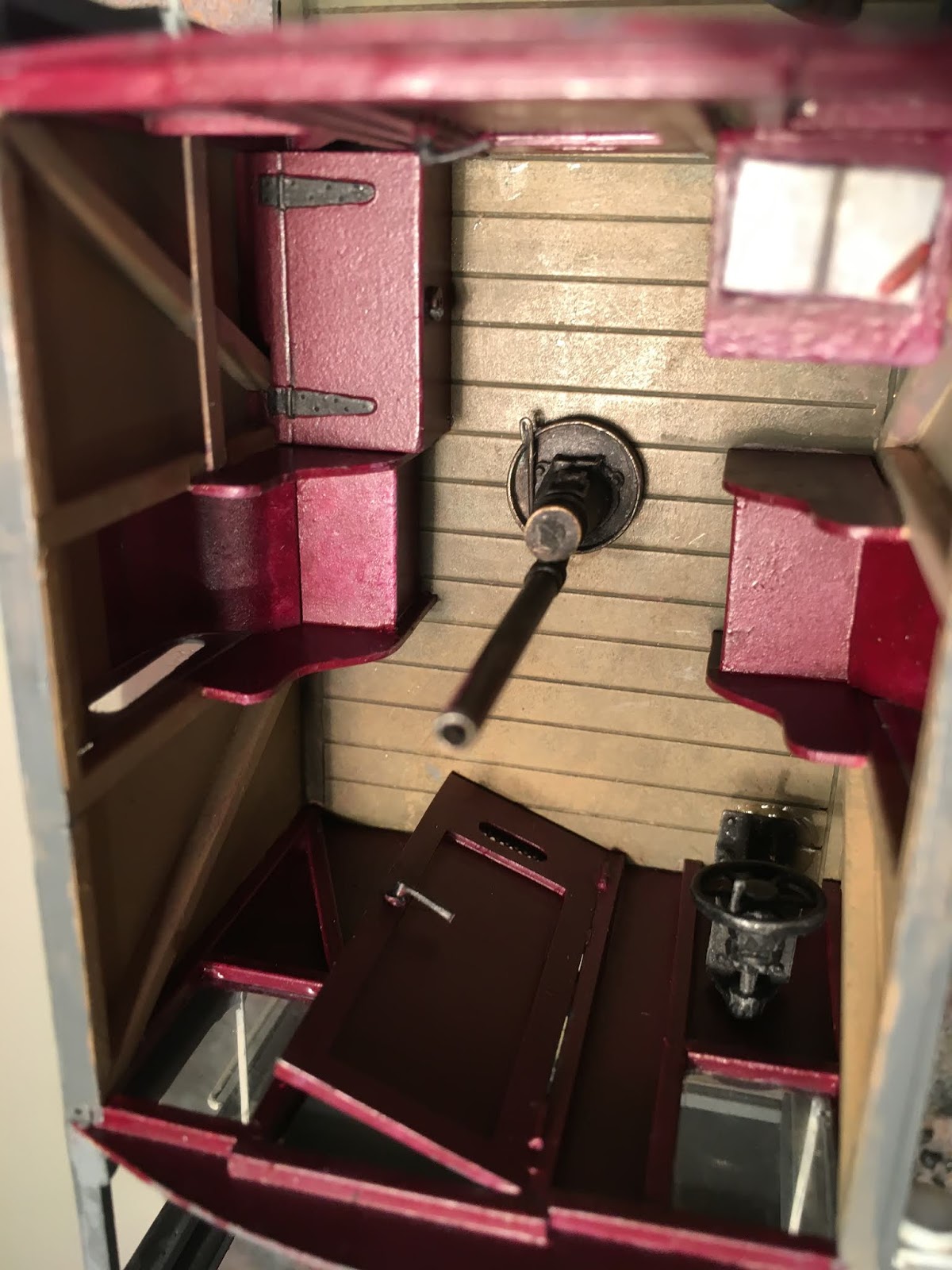
Cab floor in place with locations for square wooden inserts on the upper level. The distance between splashers on the real engine is a miserly 4ft 3". The model splashers are only 3ft 10" apart, leaving even less working space for the crew.

Slaters' brass hornblocks slide in slots in the 0.7mm frames and are held in place by an "L" shaped keeper plate.  

The frames stop short of the open footplate behind the buffer beam. The wider cosmetic front frames are attached to the footplate and overlap the working frames in an obvious manner though when the wheels are in place the join is hardly noticeable.

Tuesday 27 November 2018

Passenger Tank HR46 Complete

HR 46 Passenger Tank

Number 46 was built 2/1906 and entered service on the Highland Railway in unlined Drummond II green livery which it retained until taken into LMS service when the engine was painted red and numbered 15054. The model is built without the aid of a kit though it relies heavily on commercially available castings, mostly from Laurie Griffin Miniatures.

Cab doors open and close, a sneck locates over the stanchion to lock them in place. 

The bogie splashers are attached to the engine main frames which causes a clearance problem with the rear wheels on curves. I made the splashers as near scale as possible and after much fiddling and filing, a film of Araldite on the inside and some restriction of the throw of the bogie, the engine corners well now, though I don't think it will negotiate very tight curves.


Cab Interior with crew from Invertrain Models.

Most of the castings on display in the cab are from LGM, they are invaluable as making absolutely everything yourself is a very long way round. However nearly all the castings have been modified in some way or other to suit this particular engine.

The crew are from Invertrain's "Heroes of the Footplate" range and are chosen for their poses, which suit the small working space, they contrast with each other and don't crowd the cab. The driver's hands are over the cab beading and hold him steady when the engine is in motion. The fireman's feet are soldered to a small metal base, painted to match the wooden floor; double sided Sellotape holds him in place. Both figures can be removed from the cab without damaging any paintwork.

Transfers from Fox; number plates from Guilplates.

My next locomotive building project deviates for a change from the HR into the LNWR. Work is underway though not far advanced yet.
It's "Merrie Carlisle" a Precedent class engine which in LMS days ran in their very attractive red livery.
So watch this space...

Tuesday 23 October 2018

G & S W R 16T Drummond Brake Van complete

Photo from the archives of the G & SWR Society.

The G & SWR Society kindly supplied the above photo from their archive of the brake van in pre-grouping livery which I used to complete my model. I drew the number and maker's plate by hand then scanned the drawings, sized them on the computer and printed them on the inkjet. Transfers are HMRS from their sheet no. 20. 


Drummond 16 Ton Brake Van
 
The mid grey colour of the van is of my own devising. I have outlined the panels and planks with a darker shade but have not carried out any weathering. The van measures 120mm overall and weighs a chunky 300g... and runs superbly. Note that the lower foot boards have been thickened to 0.9mm which is near the inch and a half of the real thing. 


Note the lamps in place and guard on the look out.


I painted the end of the van red which I think is possibly correct for a van in pre grouping livery. It also adds to the attractiveness of the colour scheme. The van ends featured curious double doors which opened outwards, their purpose escapes me. The roof, which can be removed to view the interior, is held in place by a screw in the chimney which locates into the top of the stove pipe inside the van. The guard in his red trimmed cap is from a "Heroes of the Footplate" figure, he has been repositioned slightly to fit into this particular van.


The interior is fully furnished and fitted.


The brake van is of the single skin variety, there is no inner planking so the structural framing is visible and has to be modelled which is probably a more onerous undertaking than furnishing the van. No helpful information has come down to us from G & SWR days, which leaves the field wide open to the imagination, so I opted for a contrasting maroon and cream interior and avoided any horizontal colour divisions as this would have been too difficult to paint in the confined interior. The floor planking was painted, dry brushed and lined and in turn contrasted attractively with the maroon fittings. I used a lot of masking tape when I painted the interior and left the window glazing until last so I could access the interior by poking my brushes through them. Only the stove, the inner brake mechanism and the corner storage box were painted separately and glued in place later.   


Wednesday 12 September 2018

HR56 The Dornoch Tank...Painted

HR56 Drummond II livery 1902-1912


I considered how I was going to overcome the problem of the name "Dornoch" on the tank sides before I even started this project and discovered that the series of names for Highland Railway engines produced by Guilplates included "Gordon Castle", which contains all the letters I needed except the final "H". The missing letter was located on Guilplates' transfer sheet for HR locomotives, which included the wording "Highland Railway" in several different sizes, one of which provided a suitable "H".

The gold lettering of the Highland is shaded in two tones of green and outlined with both black and white, so is not easy to reproduce in miniature. Guilplates design of these letters is somewhat wayward when examined closely, however it is the only option in this case and I think the result is reasonably convincing.

The HR lettering produced by Fox Transfers is not compatible with that of Guilplates, though the Fox transfers are crisply printed they omit the darker green shading which is printed black.


HR56

Cab interior with real coal spilling from the coal hole.


Phoenix Precision paints' P727 Dark Green (1885-1912) was used to represent the Drummond II livery. Floorboards are made from wood strip from a model ship kit. The buff colour of the upper cab sides is Revell matt 82, a useful brown, mixed with white.

The "Archer Surface Details" rivets on the boiler fairing in front of the cab are in evidence in this photo and are I think most effective.


The front spectacle plate can be removed which much simplified painting. The backhead fittings have been left as buffed brass which contrasts with the black backhead plate. 

More resin transfer rivets can just be made out above the rear windows. Builder's plate from Guilplates though barely legible.

Loco lamps from Laurie Griffin, rather undersize, drilled and fitted with a brilliant.

The red loco lamps along with the brightwork and transfers alleviate the austerity of the Drummond II livery.

Tuesday 7 August 2018

HR 56 Dornoch Tank construction complete

HR56 Brake cylinder and associated mechanism.


It often takes longer to work out what you're looking at and how to make it than to actually do the job and the brake mechanism of HR56 is an example of this. The brake cylinders and the link to the transverse brake shaft, which can be seen just behind the rear wheel, are the same on both sides, however on the right of the engine only, just in front of the brake cylinder there is what seems to be a tap, possibly for drainage of the system. The detail here was derived from photos and from Charlie Wrigley's article on the braking systems of the Stroudley Tanks in HRJ 107. It's all a bit of a tight fit leaving no room at all for a rear sanding mechanism.


Brake mechanism, coupling rods and brake pull-rods on display.

Inside the cab, directly above the brake cylinder on this side, is the brake standard. A threaded operating rod can be seen between the brake cylinder and the drain tap which is connected to the transverse shaft inside the frames by an operating arm.

The rods connecting the brakes across the engine are made from 1.2 mm tube. The brake pull rods are screwed into the tub with 16BA cheese heads and can be removed. A spot of solder in the tube ends, which is then drilled and tapped, secures the screws.

Coupling rods are jointed and made by Premier Components, however they had a flat profile and had to be shaped between the bosses to improve their looks, a job that necessitated the purchase of some new files as the metal of these rods is hard.


ABCGears Mini 7S with M1824 motor in place.


The brake pull rods are bent both outwards and down slightly to allow clearance for the coupling rod bosses. I cut these from 0.4 nickle silver sheet, making a crenelated shape in the flat which allowed for the downward aspect of the rods. All bends were then made in the vertical plane and the holes drilled afterwards.
The motor and gearbox as fitted does not leave room for a flywheel inside the superstructure, it is in fact the wrong mechanism for this engine so is due to be replaced with an ABC Mini Gooch with the same M1824 motor which will allow for a flywheel which will maximise the engine's running qualities.
A glimpse of the inside workings is afforded by the cut-out behind the front driving wheels. I did not model the inside motion fully, however I did solder representations of the connecting rods in place between the frames to give some impression of the works within.

HR56 Cab interior.


The brake standard can be seen on the right of the cab. The coal hole door is open and real coal will be added later to the Milliput base. The rivets on the boiler fairing are from Archer Surface Detail, these are resin transfer rivets, they are the largest I could find and have been used above and below the cab windows too. Though prominent at this stage, when painted they will be mere pimples which is probably appropriate at least for those round the windows.


Milliput base in bunker to which real coal will be added. The Highland Railway added the bunker c.1910.


Smokebox and buffer beam detail.

The route that the vacuum pipe follows perplexed me somewhat as it is not apparent on photos of the engine and vacuum pipes do not appear on the Ward drawing of no.57 to which they were never fitted. After a good deal of thought I decided that the pipe must run along the underside of the buffer beam, then go up to footplate level and run inside the vallance on the right of the engine.

The buffer beam is a sandwich of nickle silver outers with a Milliput filling to simulate the wooden beam of the original. The sprung buffers are from Walsall Model Industries, the buffer housings were detailed by the addition of hex bolts supplied by Prime Miniatures.


Laurie Griffin supplied the HR lamps to which I added the brilliants.


The wide cab opening allows a good view of the cab interior detail.

The rear coal bunker was added to HR56 around 1910 and at the same time the lamp irons on the rear buffer beam seem to have disappeared. The rear windows were rather longer before this time too and seem to have been made smaller in response to the addition of the bunker.


 Vacuum pipes and wheels with diametrically opposed holes on all drivers are an identifying feature of this engine. The gap between side tanks and cab forward extension is another characteristic feature of HR56.

When the HR revised the braking system of HR56 (1896?) a front brake was added. As built the engine had brakes only on the centre and rear wheels so the change involved moving the guard irons forward to make room. I discovered this when I came to fit the brakes to my model. I originally positioned the guard irons from the Ward drawing, which shows HR57 as built, so when I came to fit the brakes I had to move the guard irons forward; photographs of the engine confirm the new forward position of the guard irons.

The completed engine, with a little weight in the side tanks and ash pan, weighs in at 600g. Her pulling power should match that of the real engine though a run on the CDOGG club layout in Carlisle should clarify this.

My aim in scratch building this little engine has been to build the best model I can with no concern for time taken nor for that matter the cost. I hope it might even be the best model of the engine yet built, I just don't know...and anyway I doubt whether many HR56's have ever been built in 7mm scale. As to the cost... a conservative estimate would be an outlay of £400. On the credit side the project has afforded me many hours of involvement, amusement and pleasure, though tempered with moments of anguish, frustration and despair. And... I've learned a lot. It all adds up to the conclusion that £400 is a mere trifle.

Tuesday 10 July 2018

Dornoch HR56 more progress.

HR56 superstructure nearing completion, the smokebox dart arrived from LGM this morning.

I chose to build a second model of one of Stroudley's Lochgorm Tanks simply because they make a very attractive and jolly little model. It would not be exactly the same by any means as all these little engines differed in detail. I had quite a few parts in hand, including an ABC motor-gearbox as well as a set of etches for the wheel overlays, which gave the project a flying start. The first HR Stroudley Tank that I built was a model of HR57, this was in 2013. This particular engine is comparatively well documented as there are far more photos extant of Lochgorm than of her other two sisters in the class. My choice of a second engine fell on no.56 rather than no.16 mainly because there exists a very detailed photo of the former in HR days as the Dornoch Tank and in addition I have the transfer lettering for the name Dornoch to hand. In all I unearthed five pictures of Dornoch in HR days and six of her in LMS livery, not all of which were uniformly helpful; perhaps this dearth of pictorial evidence is the reason why so few models of either 56 or 16 are built in gauge 0. Nevertheless, these few pictures provide enough information to build an authentic and well detailed model. My primary reference was the Laurie Ward drawing of Lochgorm in original condition, to which I added the differences, culled from the written record as well as from photographs, which characterised Dornoch. There are a surprising number of differences between the three engines of the class, particularly in the braking arrangements, which I'll deal with in my next posting when the chassis is complete.

HR56 was built in 1869 and originally carried the name Balnain, the others of the class, HR 57 and HR16 were built in 1872 and 1874 respectively. My model takes up the story of HR56 in about 1910 when, now named Dornoch (1902), a rear bunker was fitted in place of the tool box. In 1917 the tank which arched over the boiler was extended back to the cab which did little to improve the appearance of the engine which was compromised further in 1920 when the HR modified her elegant Jones chimney by adding a clumsy flared top.

Most of the brass and nickle silver castings used in the model are from Laurie Griffin (LGM) who, I believe, intended to introduce a kit of this engine into his range and though this never materialised, the castings for the kit did, which is a great help. Agenoria Models produced a rather dubious kit for a Lochgorm Tank, though it is no longer available. My own model of HR56 is built without the aid of a kit which not only lessens expense but also cuts out the aggravation of wrestling with a bottom end of the market kit.

In the Blog Archive in the right hand column you'll find postings from July 2013 which cover the building of my earlier model of HR57 Lochgorm in some detail.


A rear bunker was fitted to HR56 in 1910 and the previous coal space in front of the cab was faired over and given a hand rail. The rear lamp irons were removed at this time and the rear cab windows modified becoming square rather than rectangular. The removable roof is a modified white metal casting from Laurie Griffin Miniatures.


The coal hole has a vertically sliding door. In the cab corners are what I think are sand boxes though by 1910 braking arrangements left no room for a rear sanding mechanism.


There is an inner skin to the front cab plate to which the boiler back-head attaches. The whole assembly can then be removed for painting. Wooden flooring is made from model ship planking.


Awaiting the smokebox dart which arrived today from LGM. Note the triangular bracket right of the coupling hook which accommodates the vacuum pipe, though the route that this takes out of sight remains uncertain, I think it probably runs behind the footplate valance. The coupling hook is made from 1.2mm sheet n/s, the single link comes from my spares box.


Not a great many models in gauge 0 have been made of HR56. Note the 2" gap between the water tank and the cab forward extension. A fairing, oversailing the boiler, provides seating for the dome and safety valves.

Wednesday 9 May 2018

HR56 Dornoch, progress

A coal bunker was added in 1910 with a coal-hole in the cab.  


The original bunker of HR56, which was in front of the cab spectacle plate, was sheeted over and a hand rail added to match that on the other side when a rear bunker was added in 1910. The new coal bunker replaced the tool box behind the cab and photographs suggest that at this time the rectangular rear cab windows were remodelled rather smaller and square, similar to those at the front and a mesh screen was added to protect the glazing. In addition a coal-hole was added which I've given an elegant vertical sliding door similar to that seen in Stroudley's later Terriers, which he designed for the LB&SCR

There is a 2" gap between the front saddle tank and the original bunker which is not evident on the other two HR Stroudley tanks, only Dornoch displays this. A fairing, on which the dome is mounted, covers the boiler in front of the cab and partly covers the gap. There is an outer and an inner cab front between which the glazing will be sandwiched. The boiler backhead, which for want of information, takes as its model that of the related Stroudley Terriers, is mounted on the inner sheet and this assembly will be removable.


HR56 showing progress to date, chimney and dome from LGM.


My intention is to complete the sheet metal work first and then add the castings and fine detail. The cab is still joined to the bunker assembly by a structural device which ensures accuracy of construction, this will be removed when the structure is complete, before the cab stanchions are put in place. The buffer beam on these engines was a sandwich of metal plates with a wood filling which I hope to replicate. I intend to experiment with Milliput coloured with weathering pigment, to simulate the wooden part as I find real wood, box in this case, hard to work and rather toy-like in appearance.

The frames of the engine are 27mm wide and are cut short just beyond the front driving wheels. The frames are visible in the gap in the footplate between the smokebox and the buffer beam, so they are modelled full scale (actually 29.5mm) and attached to the footplate behind the buffer beam so they fit over the working frames. The join between the dummy front frames and the working frames will not be visible as the front brakes cover it. The smokebox front plate extends below the buffer beam to the cylinder covers so there's a lot of detail in this area and I intend to maximise its potential...

Thursday 12 April 2018

A New Locomotive Project, Stroudley HR56 Dornoch.

 All 6 of HR56's wheels are similar and solid with 2 small opposed holes. 

Three 0-6-0T engines to William Stroudley's design were constructed at Lochgorm Works, the first and the subject of my model was number 56, built in 1869 and originally named "Balnain". The engine was substantially rebuilt in 1896 when it gained its Jones chimney. By 1910 a rear bunker had been added and the engine, renamed "Dornoch", was turned out in unlined olive green livery, which rather suits my painting skills. In 1917 her good looks were compromised when the tanks were extended back to the cab, thus drawing a line under my interest in the engine. My model will be built to illustrate HR56 in the condition in which it ran between 1910-17.

Photos of no.56 in Highland Railway livery are in short supply, I have found five though non of these shows the engine in my chosen time slot. There are a further six photos extant which show the engine in LMS days and these are of value as they show details inherited from earlier days. The model will be scratch built, though it will depend on castings from Laurie Griffin, who made fittings for a kit which never materialised, and without which my model would be a non-starter.

HR56 is in most respects similar to HR57 "Lochgorm" and a  drawing by Laurie Ward of the latter is my starting point. There are a surprising number of differences between the sister engines each of which will be noted and incorporated in my model. In addition to Laurie's drawing there is a very useful article by Charles Wrigley in HRJ 107 (Autumn 2013) concerning the differing braking arrangements of the Stroudley tanks.

The chassis has already had a test run on the club layout in Carlisle and proved a good runner. The motor gearbox is an ABCgears Mini7S with an M1824 which provides ample power though there is no space for a flywheel. Pick-ups are wires bearing on the back of the left hand wheels while the wheels on the right hand side are shorted out.

The overlays to the wheels are etches from my own design left over from building HR 57 some time ago.

Saturday 7 April 2018

Klondike brake van in action.

 HR Klondike brake van at CDOGG
Stroudley Tank and Klondike brake van in the scenic section of the CDOGG layout.


Hauled by Highland Railway Stroudley 0-6-0T number 57 "Lochgorm" my newly completed Klondike brake van was in action today on the Carlisle club layout and a very fine pair they looked together.

Saturday 10 March 2018

Klondike brake van in grey Primer

Klondike d.24 brake van in Halford's Acid 8 primer.


There's a rectangular recess to take a blackboard on this side of the van below the handrail which carried the name of the guard and the station of origin of the van which my wife says she'll contrive on her computer. The vans were numbered 1-19 and painted red oxide, the number in white appearing on the side ducket. I think it'll be an Aberfeldy van in the charge of either R. Bruce or W. Wallace.


Klondike van viewed from the step end.

Friday 9 March 2018

HR d.24 Klondike brake van.


HR d.24 brake van c.1900

Though these vans seem to have plenty of room inside for packages and consignments of small goods the single 2ft 3ins wide door seems unnecessarily restrictive, a comparable design of similar length belonging to the neighbouring GNoSR has double doors which must have made goods handling far easier.

The interior of this van was probably much the same as that of the restored Highland Passenger Brake Van No.5. I did not build an interior however as I thought it lacked the interest provided by my previous G &SW brake van project.

The roof can be removed to fix the glazing in place, it is screwed to a cross-member which is located just below the top of the side wall, the fixing screw is concealed inside the holder for the lamp hole bung, between the chimney and the lamp top.

Lamp irons are replacement brass castings from Slaters and will support a lamp, one of which can be seen on the step-end of the van.  I made the couplings, both hooks and links myself, the wide shank of the hook fits nicely in the deep slot in the buffer beam. The safety chains, which went out of use, about 1901, hang from slimmed down hand rail knobs mounted either side of the draw plate.


Highland Railway Klondike brake van.

The sole-bars are inset a few inches below the van sides, not flush with them, a feature which shows up on photos but is not allowed for by the kit. Narrowing the gap between the sole-bars to the correct width creates another problem...the rocking axle won't rock! A good deal of judicious filing is necessary to reinstate this feature. The buffer beam needs to be redesigned altogether both to fit the narrower gap between the sole-bars and to conform to the prototype drawing.
I replaced the cast white metal springs provided with ones of my own design which I originally modelled and cast for Lochgorm's earlier Open Carriage Truck kit, this allows more clearance between the bottom of the sole-bar, on which the springs are mounted, and the axle bearing, some modification of the axle-box castings was also needed to fit them into the space available.


The rocking-axle end of the van.


There appears to be no sign of a vaccum cylinder beneath the van on the photos that exist which simplifies matters below the sole-bar. The corners of the axle trays are cut away to make space for the buffers and similarly a central cut-out allows for the coupling spring. The couplings have been chemically blackened, the hook and its spring are retained by a transverse pin. The main advantage of a sprung coupling being that it facilitates removal when the van is being painted.

Pete's next brake van project will feature a fully detailed interior complete with a guard...so watch this space!


Thursday 8 March 2018

G & SW Brake Van in primer

G & SW brake van in Halford's Acid 8 Primer.


G & SW brake van from a Taff Vale/Dragon kit with improvements and interior detail.

The rather scrappy appearance of the finished brass model is much improved by a unifying coat of Halford's Acid 8 primer. The wheel treads have been masked off with Tamiya masking tape, the buffers and couplings have been removed and chemically blackened. The running gear and footboards, all below the solebars in fact, will be airbrushed matt black though the remainder of the model, including the interior, will be hand painted.

Tuesday 23 January 2018

Joy's Valve Gear for an LNWR Precursor Tank

Joy's indirect valve gear module.

The removable valve gear unit seen here is built from a set of nickle silver castings produced by LGM. The mechanism is non-working or cosmetic, it does not include a crank axle nor the connecting rod big-ends, though the front parts of the connecting rods, which attached to the piston sliders, are present as the swing links and their dependant linkages are attached to them below the radius block. Only the "front end", that is the parts of the valve gear that can be seen below the boiler, has been modelled. The jointed, pivoted and sliding parts of the valve gear do indeed move, they're not soldered solid, so it's as near working as possible and everything moves in an appropriate manner if you tweak the connecting rods. I think with what I've learned making this model I might be able to build an actual working set for a future project. Laurie's instructions are helpful though I found the best guide to building Joy's valve gear was Geoff Holt in "Locomotive Modelling" Part 1.
The centre frame member, which protrudes to the rear of the motion plate, provides a third point of support to the crank axle in the prototype. In the model the inverted "U" shaped cut-out provides clearance for the front axle.


It's a busy place between the frames under the boiler and rather murky too!

If you peer carefully under the boiler you'll find that quite a lot of the valve gear is in evidence, in addition the anchor link and its supporting stirrup are visible below the frames, behind the front brakes and below the sand boxes. The brackets which carry the transverse shaft, on which the anchor link is mounted, are attached to the lower slide bars, these are out of site though they have been situated and designed so as not to foul the bogie wheels on corners.


Joy's Indirect Valve Gear in situ.


Joy's indirect valve gear adds another layer of complexity to an already fiddly business by the inclusion of rocking levers, seen here between the curved radius rods and the valve spindles.

The red electrical wire that can be seen is a pick-up wire, which is struggling to find a way through the valve gear to its connection on the front bogie.