Scratch built by Pete who also made the crew, exterior paintwork and lining by Paul Moore.
Slaters wheels running in sprung hornblocks, rear radial axle slides in curved guide similar to prototype, jointed coupling rods.
Pick-ups are split axle on front drivers with wire pickups bearing against rear face of centre and rear wheel.
Mashima M1833 motor with flywheel and ABC Gears gearbox.
All brass fittings, no white metal castings other than tool boxes.
Constructed so that the bunker and cab rear as a unit can be removed to allow access to the cab, the roof is also separate.
 |
| LNWR Coal Tank 771 with shed plate for Workington |
 |
| No 771 as she appeared in the 1890s |
 |
| Cab interior and crew painted by Pete. |
 |
| Cab interior of the 1890s before the fitting of carriage heating equipment added even more complexity to the pipework! |
 |
| Detailed cosmetic inside motion is included, couplings from CPL. |
 |
| Pete's Coal Tank at CD0GG recently |
April 7, 2012
Coal Tank rear wheels
I’ve had a photocopy of an interesting article from MRJ by Laurie Griffin entitled "Radial Axleboxes" laying about in the studio for some time. I glanced through it a couple of times and thought it seemed a daunting undertaking, especially drilling out the axle holes. Then I realised that if I used a pair of LGM brass hornblocks I wouldn’t need to drill any holes and I’d have a flying start.
 |
| Radial axle |
The radial axle assembly…LGM brass hornblocks were filed to shape to slide laterally in the curved guides. Springs were mounted as shown to stop the wheels moving too much and touching the frames. The wheels are insulated and the split axle you can see will be replaced with a solid one. I don’t think I’ll be able to devise a method of fitting pick ups to these trailing wheels.
 |
| Radial rear axle in place |
Here’s the radial axle in place with the side control springs acting between the frames. A screw through the curved guides below the axle keeps it from falling out. I tested the chassis with the trailing wheels in place and was quite astonished when it negotiated three sets of Slaters’ points and the 5′ 6" radius curve on my test track in both directions without a problem!
April 3, 2012
Coal Tank running
 |
| M1833 and ABC Gearbox in place |
The Coal Tank is up ‘n running and though at this stage there are only temporary wiper pick-ups on the rear and centre pairs of driving wheels she’s running quite well. The slide-bars are in place and have been cut away slightly so they don’t foul the front hornblocks. I’ve taken a wire from the tiny pierced pick-up tabs at the front of the motor to a piece of copper clad insulation board glued to the side of the motor to create a working platform. From here a wire is screwed to more insulation board under the motor which allows it to be removed without unsoldering any wires. A soldered wire leads down to join the pick-ups which are mounted on ccib fixed to the bottom of the ash-pan. The front wheels are shorted out and mounted on a split axle which runs in Slaters’ insulated hornguides, so I hope I can run a wire back from the brass hornblocks to the motor.
 |
| Slide bars in place |
I had to widen the wheel slots in the footplate before the superstructure would mate happily with the chassis. Here you can see the slide-bars in place between the frames… above them, attached to the frames just in front of the motion plate are the lugs that will carry the transverse shaft on which the reversing weights are mounted. The Coal Tank has a long wheelbase when the rear trailing wheels are included. At the moment the engine is running as an 0-6-0. I can see that getting it to run as an 0-6-2 is going to prove rather tricky. This is the next problem I intend to address.
March 20, 2012
Coal Tank superstructure
 |
| Frames sandboxes and splashers |
The frames are visible in the gap to the rear of the buffer beam, they curve upwards above the footplate where they support the rear of the front sandbox. A triangular ash hopper can be seen between the frames, below the footplate, though most of this will eventually be masked by the cylinder front plate when it is in position.
 |
| Cab with etched brass window surrounds |
 |
| Cab with LGM backhead in place |
The stepped circular brass window surrounds show to good effect here. I made the cab steps at the weekend which more or less completes the basic structural work; behind the step is a cut-out in the frames that I only became aware of recently. I found the steps time consuming…symmetry eluded me, the rivets refused to line up and the pile of discards mounted, matched by my rising irritation…I cracked open a bottle of Jennings Cumberland Ale and put my feet up; it was the only solution to a bad modelling session.
The tank top beading is made from n/s strip which I had to file to shape as it swells slightly at the ends, below which a tiny washer adds strength to the joint between beading and stanchion.
 |
| Chassis and superstructure mated |
The bunker and cab rear unit is held in place by two screws from below as I’d like this to be removeable for access to the cab. The rear cab stanchion will be attached to the bunker top beading and fit into a hole in the footplate as it will have to be dismountable too. The cab roof will be soldered to the cab front but only rest on the cab rear plate…well I hope the idea works, I just can’t tell at this stage.
March 7, 2012
Coal Tank details
 |
| Structure inside tanks |
February 29, 2012
Catching up

I’ve caught up with where I was last time I posted about the Coal Tank on February 10th. You’ll remember I had to take most of the body apart to make a narrower running plate. In fact I’ve made progress, not only has the engine a new scale running plate but I’ve built the basic structure of the bunker and made sure that it’s flush with the side tanks. I’ve done a lot of measuring to make sure the basic proportions of the various sub-assemblies are correct and made a few necessary adjustments. From this angle, with the front splasher/sandbox assembly in place, you can see the empty space under the boiler where the balance weights will add interest between the frames; these are carried on a transverse shaft between supporting brackets already in place. The next stage is to finish the side tanks and to try and devise a way of making the bunker dismountable, otherwise I’ll struggle with the cab interior which I’d like to model in some detail.
February 10, 2012
One step forward and...
The progress I’ve made on the Coal Tank’s inside motion is a step forward, and it’s complete. However, I’ve made a few backward steps too since my last posting.
 |
| Stephenson's inside motion |
Progress on the inside motion was not matched by progress on the superstructure, quite the reverse. You’ll remember that I managed to salvage the etched footplate from the ancient Mercian Models kit that I dismantled, and that I used it as a basis to start assembly of the superstructure. This was a mistake. I discovered that the boiler located on it a scale 3" too far back, it doesn’t seem a lot, you might think I could’ve got away with it, nobody would notice. But when this error was compounded by my locating the bunker too far forward as well the result was disaster; the cab was 6" too short. The cab of a Coal Tank is minute anyway, with no room to swing a shovel, and I’d shrunk it to impossible proportions. This discovery put progress into reverse. I realised that I’d have to move the boiler forward 3" and the bunker back the same distance and that then I’d have my 6" back! The upshot of this discovery was that I had to dis-assemble the engine, the tanks came off easily enough and I managed to gently prise the boiler and smokebox off the footplate undamaged with judicious use of the gas torch. As the disgraced footplate sailed across the workshop into the waste bin it occured to me that it would have been quicker, and a good deal cheaper, to build a Coal Tank from scratch in the first place.
I might have taken a couple of backward steps but, "nil desperandum" I thought, as I leaned back in my chair and opened a bottle of Jennings’ Cumberland Ale… "a couple of these’ll put things back on track all right".
February 1, 2012
Coal Tank recent progress
January 19, 2012
Coal Tank Crew
 |
| Coal Tank at Workington CRA Photo |
The Cumbrian Railways Association sent me this photo of a Coal Tank at Workington about 1897 shunting in the yard with driver John Young and fireman A Shepherd in the cab. I thought that when I came to make a model "Crew for a Coal Tank" I’d model this pair. The driver seems to be standing on one of the wooden plinths that flank the firedoor and the fireman standing in the doorway is in just the right place for an engine that has very little space in the cab. Both seem to have some sort of uniform cap and it’s possible that the fireman’s jacket was issued to him by the LNWR though it’s hardly "uniform" as there’s no insignia of any sort to be seen. Note the double buffers on the brake van.
January 17, 2012
Coal Tank progress
Photo Copyright Cumbrian Railways Association.
January 13, 2012
Threlkeld Station
 |
| Therlkeld Station staff CKPR |
 |
| Threlkeld Station staff ; CRA collection |
These two photos taken at the same time show some of the staff of Threlkeld Station on the CKPR along with a Coal Tank and its crew, both photos are now in the collection of the Cumbria Railways Association. I discovered some details about the porter, fifth from the left here, sitting on the tank top above the painter. In the top photo he’s standing fourth from the left. His name was Joseph Hebson, a local lad, who served with the 5th battalion of the Border Regiment on the Western Front where he was killed on the Somme in 1918. His name is included on the Pozieres memorial. The Coal Tank was probably from Workington where there were fourteen of these engines on shed in 1912, the fireman is on the far left of the picture and the driver sits on the footplate by the smokebox with folded arms.
Photo: Copyright Cumbrian Railways Association: Kerr Collection
January 7, 2012
LNWR Coal Tank Project
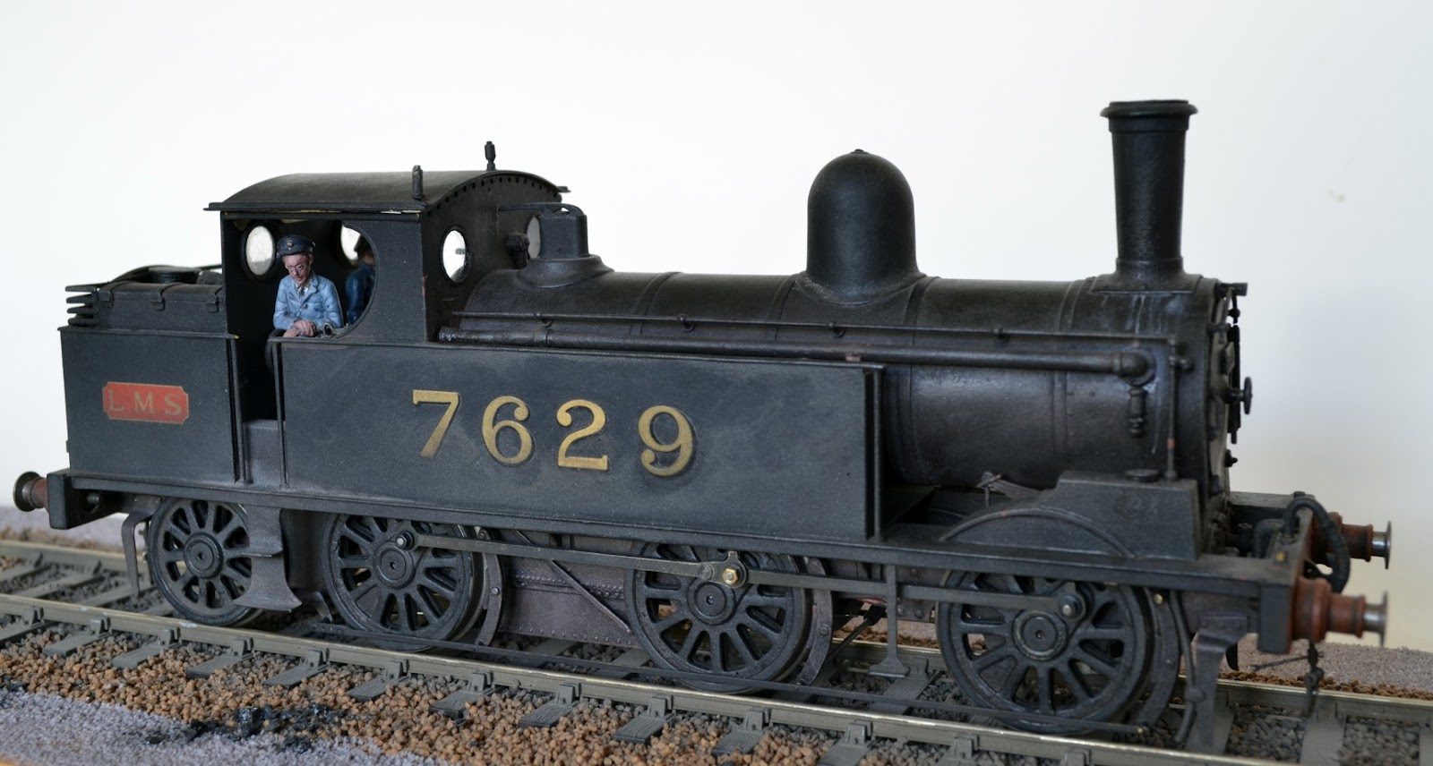 |
| "my first 0 gauge engine" |
Pete Skellon’s new book on the NW Coal Tanks revived my interest in these engines and I thought that I’d take up the thread again where I left off and make a few improvements to 7629…a fly wheel, perhaps a new chimney and maybe a cab interior. I set to work and realised that I’d have to strip the paint off the model too but thought that a new paint job wouldn’t come amiss anyway. I stripped her down to bare metal and took the old white metal chimney off. Then…one thing led to another; the boiler bands came off, the boiler back was prized away, out came the gas torch and before long there was nothing but a pile of bits ‘n pieces.
I decided that now I had Pete Skellon’s book in hand I could build a real scale model of a Coal Tank. There were a few good LGM castings and the odd salvageable etched shape from the old model that would give me a start… so make a start I did. I’ll show you how far I’ve progressed in my next posting soon…
No comments:
Post a Comment